I had to program many types of microcontrollers over the years and so I was thinking why not build a simple programming rig to make things easier. This rig is for the In-system programming (ISP) method and not for the UART method.
The board in the above image is not the programming rig but a digital clock shown as an example. Notice the 6 pin header near the cap. The pins are not soldered through hole but on SMD pads. This way it can be easily de-soldered after finishing the project and on some space constrained projects this is a must.
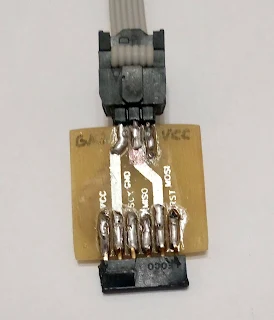
Here the ISP programming rig is connected to the board. The other end of the board is connected to the USBTinyISP using a 6 pins two rows header.
ISP programming rig schematic
The schematic is very simple - just 1 row of 6 pins receptacle and 2 x 3 pins header. On every project the 6 pin header must have the pins connected in the order indicated by the schematic. A marker can be placed on both boards to indicate the VCC pin to prevent the board being plugged in in reverse which could burn the microcontroller if there is no input protection for reverse voltage.
Schematic and PCB for DipTrace download
ISP Programmer Rig.dch and ISP Programmer Rig.dip


No comments:
Post a Comment